
Core & Cavity Modeling in Pro-Engineer.
USEFUL FOR COMPLEX MOLDED PARTS
- Approaches part modeling from a tooling perspective.
- Uses 3 basic parts to create a final product
- Core – the male part of a mold
- Cavity – the female part of a mold
- Part Body – the solid that the core and cavity act upon
- This approach simplifies modeling irregular and complex geometries
DEFAULT COORDINATE SYSTEM DEFINES THE GLOBAL ZERO
- This is necessary when using the “Design in Place” approach.
- All major components have the same Zero
- Assembly placement is within parts by the relationship between the geometry and the Zero
- Global Zero is not used for:
- Assemblies that rely on constraints
- Components shared between multiple assemblies, for instance screws

PART COORDINATE SYSTEM DEFINES THE LOCAL ZERO
- Create a Local Zero Coordinate System
- Defined by the Global Zero
- Defines the position of geometry to Global Zero
- May be offset or rotated
- Define axis directions based on project conventions
- Create Local Datum Planes
- Based on Local Zero Coordinate System
- Base of all part geometry
- Name them after the axis that define them
- Alternate Approach
- Use skeleton geometry to define and control the part coordinate system and planes from the parent assembly
USE ONLY THE LOCAL DATUM PLANES
- HIDE THE GLOBAL DATUMS, FRONT, TOP, & RIGHT AND THE COORDINATE SYSTEM IN THE LAYERS AND SAVE THAT STATUS.
- DO NOT CREATE ANY LINKS TO GLOBAL DATUMS OR COORDINATE SYSTEMS!
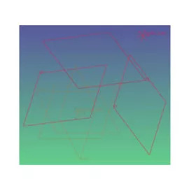
DEFINE REFERENCE GEOMETRY FOR THE PART
- Points, Datum Planes, and Axis in Addition to the Local Zero features
- Define major features of the part
- Parting lines
- Screw boss levels and locations
- Interfaces to other parts
- Screen center
- Alternate Approach
- Use skeleton geometry to define and control the part coordinate system and planes from the parent assembly
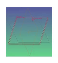
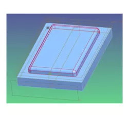
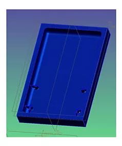
CORE PART START
- Extrude a block from the parting line
- Make the block bigger than the final part will be
- Add the basic internal shape of the part to the block on the parting line side
CORE PART DETAILS
- Add draft and rounds to features as you go
- The earlier they are added, the better the chance of them working properly
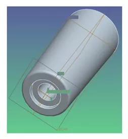
CREATE COMPLEX FEATURES AS SEPARATE PARTS
Designing as a separate part has many advantages:
- Drafts and rounds are performed on a simpler part and are more likely to work
- Common features like bosses and snaps are easier to reuse in different parts
- It is easier to swap out or remove a feature from the part model
- Interactions between the feature and complex surfaces on the part are not part of the modeling process
- The resulting part model tree is much cleaner and easier to understand
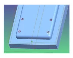
ADD SECONDARY FEATURES TO CORE PART
- Cut the secondary features from the core part
- Add rounds and drafts to surfaces created by this operation
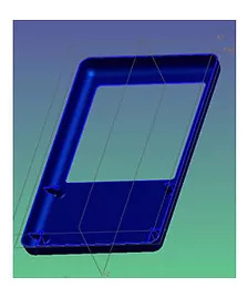
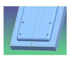
FINISH ADDING FEATURES TO THE CORE
- Cut features like ribs past the outside of the core
- This will ensure that they conform with the contours of the housing without relying on complex surface operations or rib commands
- When the core is complete, create a publish geometry feature of the solid surfaces
CUT THE CORE FROM THE PART
- The part is a separate model
- It starts out with a base block, just like the core did
- Make the block slightly larger than the desired part in all directions
- Use the cutout from other model feature
- Select the publish geometry feature from the core as the cutter
- Add any features that rely on surfaces resulting from the cutting operation
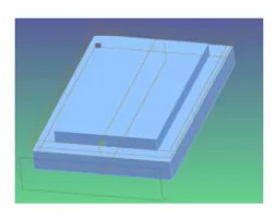
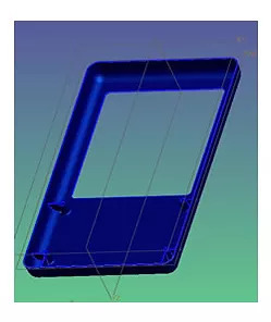
CUT THE CAVITY FROM THE PART
- Create the Cavity Part with the same techniques as the core part
- The cavity base block extrudes to the opposite side of the parting line from the core
- Separate features between the core and cavity based on their draft direction
- Add any finishing features
WORKING WITH MULTI-PART MODELS
- In order to modify a subpart it must be in either the working directory or the path
- To change a subpart such as the core, right click on it in the model tree and select open base
- The main part must be regenerated before the changes to a subpart will appear
- In order to create a copy of a part in another location, open the part and all subparts and use the backup command