NASTRAN 101.
OUTLINE
 Introduction
- File Structure
- Executive Control
- Bulk Data
- Element Types
- Element Examples
- Output Files
WHAT IS A FINITE ELEMENT 'SOLVER'?
- NASTRAN is one of many available finite element analysis (FEA) solvers
- Other solvers at Quartus: ABAQUS, ANSYS, LS-DYNA
- What does a solver do? (the short answer)
- User provides input in the form of a text file
- Solver reads the text file and performs analysis
- The solver generates output files with analysis results
- How does the user make the input text file?
- Models are created and input files exported using FEA pre/post processing software
- Various Pre/Post Processors available
- FEMAP, PATRAN, and Hypermesh commonly used with NASTRAN
WHAT IS NASTRAN?
Nastran is a powerful finite element analysis program that is used widely in the aerospace and automotive industries
- Industry standard finite element code originally developed for NASA by MSC (1960s)
- Today there are many flavors (or versions) of Nastran MSC, NX, etc.
Nastran at Quartus
- Primary program used for finite element analysis
- Used extensively to perform static, buckling, and dynamic analyses of structures
- Quartus has licenses for both NX/Nastran and MSC Nastran
- Largely the same (basic functionality)
- Some small differences and enhancements
WHAT UNITS DOES NASTRAN USE?
- NASTRAN does not have a defined unit system
- The user must be careful to maintain consistent units Units must be consistent such that units satisfy F= ma Examples for English and SI units are shown below:

Note: for English units (in, lbf, sec), the unit of mass is a ‘slinch’ (lbf-sec2/in), not a pound (lb). A slinch is the ‘inch version of a slug’. To convert from pounds to slinches you divide by the acceleration of gravity (386.1 in/sec^2)
WHAT IS AN INPUT FILE?
- At the most basic level, it’s nothing more than a formatted text file
- Defines the finite element model and all parameters necessary for analysis
- Nastran input files are often referred to as ‘decks’
- Origin of terminology comes from the time when the data was stored on actual punch cards and then fed into a machine that would read the ‘deck’ of cards.
- File extensions vary
- .dat usually used for input files
- .blk or .bdf usually used for included files
- Common text editors
- EditPad, UltraEdit, EmEditor, Emacs
WHAT'S IN A NASTRAN INPUT DECK?
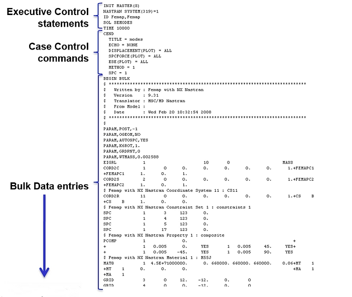
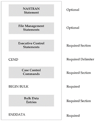
- Every deck can have 5 main sections
- Nastran statement
- File management statements (FMS)
- Executive control statements
- Case Control commands
- Bulk Data entries
- The format and definition for all entries in the input deck can be found in the NASTRAN quick reference guides
- Commonly referred to as “the NASTRAN bible”
NASTRAN STATEMENT
- This section is optional
- This section is usually used only on large jobs where modifications are needed to more effectively run the job
- Used to change parameters for the solve
- BUFFSIZE
- DMP
- Scratch file setup
FILE MANAGEMENT SECTION
- This section is optional
- File management section is used primarily for saving databases and setting up restart files
- Restart a job from a previously analyzed job to reduce solve times
EXECUTIVE CONTROL SECTION
- Executive control section is required for all runs
- Includes:
- DMAP control Section (optional)
- ID (optional)
- Identification for the Job
- SOL (required)
- What type of solution? (linear static, buckling, modes, etc.)
- ECHO (optional)
- Control whether the executive control section is output to file
- Time (optional)
- Set up max CPU time
- DIAG (optional)
- Options for diagnostic information
SOL – COMMON SOLUTION SEQUENCES

EXECUTIVE CONTROL – EXAMPLE INPUT DECK
Executive Control Section in the example deck:

This example deck performs a “normal modes” analysis.
SOL 103 = SOL SEMODES (either way will work)
CASE CONTROL SECTION
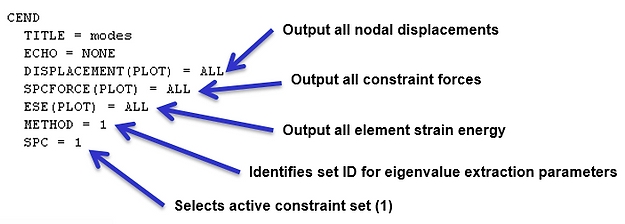
- Case control section is required for all runs. Common features:
- Selection of constraint set (SPC)
- Selection of load set (LOAD)
- Selection of eigenvalue extraction parameters (METHOD)
- Used for buckling, modes, frequency response
- Output requests
MAIN PARTS OF BULK DATA
- Nodes
- Elements
- Coordinate Systems
- Properties
- Materials
- Constraints
- Analysis Parameters (PARAM, . . . )
BULK DATA: FORMAT
The bulk section is not order dependent. There are 3 options for format (can use each type within a single deck):
- Tab delimited
- Space delimited (default, short-field format = 8 spaces/field)
- Decks written from FEMAP and Hypermesh are space delimited
- Comma delimited
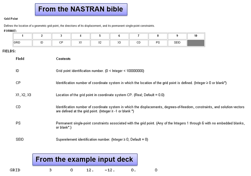
INPUT DECK NODE EXAMPLE
ELEMENT INFORMATION
5 major types of elements:
- 1D Elements: Bars, Beams, Rods
- 2D Elements: Plates, Laminates
- 3D Elements: Solids
- R-Type (rigids): RBE2, RBE3
- Connector /Other Elements: Springs, Lumped Masses
1D ELEMENTS
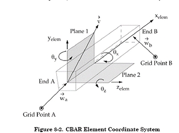 Common element types: beams, bars, rods
DOF
- Bars and Beams have axial, shear (2), bending (2), and torsion stiffness
- Bars and beams are basically the same
- Beams have more options
- Rods only have axial and torsion stiffness
2D ELEMENTS
Common element types: plates, laminates, membranes

DOF
- Plates and Laminates have in-plane (2), shear (in-plane and transverse), and bending stiffness
- Stiffness is associated with attached nodes for DOFs T1, T2, T3, R1, and R2
- No ‘drilling’ (R3) stiffness
- Membrane elements only have in-plane (normal) stiffness
3D ELEMENTS
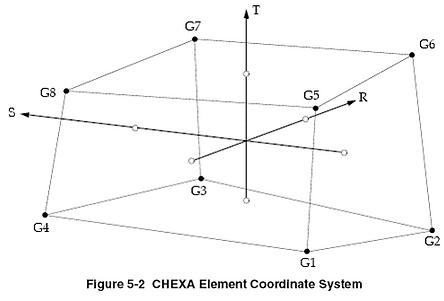 Common element types:
- Solids
- Shapes: bricks (CHEXA), wedges (CPENTA), tetrahedrons (CTETRA)
DOF
- 3D element nodes have associated stiffness in 3 DOF (T1, T2, and T3)
R-TYPE
RBE2
- Rigid element
- Infinitely stiff
- Adds stiffness to model
- No mass
RBE3
- Interpolation elements (constraint equations)
- Used to ‘average’ the responses of a number of nodes
- Does not add stiffness to model
Nodes on RBE's are either dependent or independent
- Important to be aware of dependencies
- Cannot apply boundary conditions to dependent nodes
- Nodes cannot be dependent on more than 1 RBE
CONNECTOR / OTHER ELEMENTS
Common element types: Springs, Lumped Masses
DOF
- Springs are normally used to connect coincident nodes
- Connect elements
- Recover forces
- Two main types of spring elements
- CELASi: connects only 1 DOF
- Multiple elements are required to connect more than 1 DOF
- CBUSH: can connect 1-6 DOF
- Newer, more versatile spring element
- Lumped masses are used to model mass and inertia at a node and have no stiffness
- CONMi
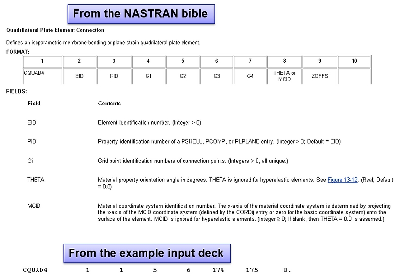
INPUT DECK ELEMENT EXAMPLE
HINGING/PINNING
Common problem when elements with different DOF’s are connected
- Plates to Solids
- Beams and Bars to Plates or Solids

COORDINATE SYSTEMS
- Coordinate systems are used to define node locations and output
- Nodes can have different definition and output coordinate systems
- Coordinate system zero is the default rectangular system located at (0,0,0)
- Rectangular, cylindrical, and spherical coordinate systems can be used in Nastran
PROPERTIES
Properties define the characteristics of the elements
- Plate thickness, beam cross-section, spring stiffness, etc.
- Properties reference materials
- Materials are defined on separate cards
Each element type has a different property
- Some elements don’t use a property but instead input the information directly on the element card
EXAMPLE PROPERTY IN THE INPUT DECK
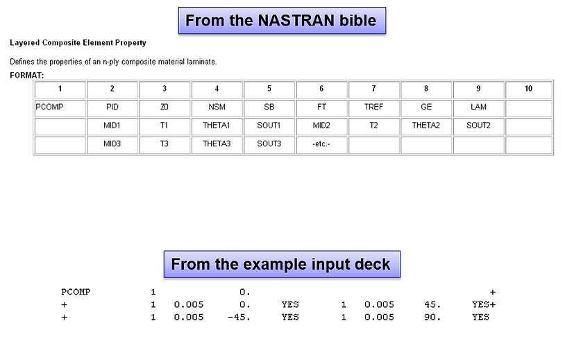
EXAMPLE MATERIAL IN THE INPUT DECK

NASTRAN FILES: COMMON OUTPUT FILES
- .op2
- Output2 File: binary file including results for FEMAP
- Most commonly used file for output
- .pch
- Punch File: results in tabulated text format
- .f06
- Text file with results from analysis along with diagnostic messages
- Can be read by FEMAP or processed by various custom programs
- .f04
- Text file containing run information; database file info, module execution summary, etc. (highly detailed log)
- .log
- Text file with general information; control file info, run time, licensing information, etc.

